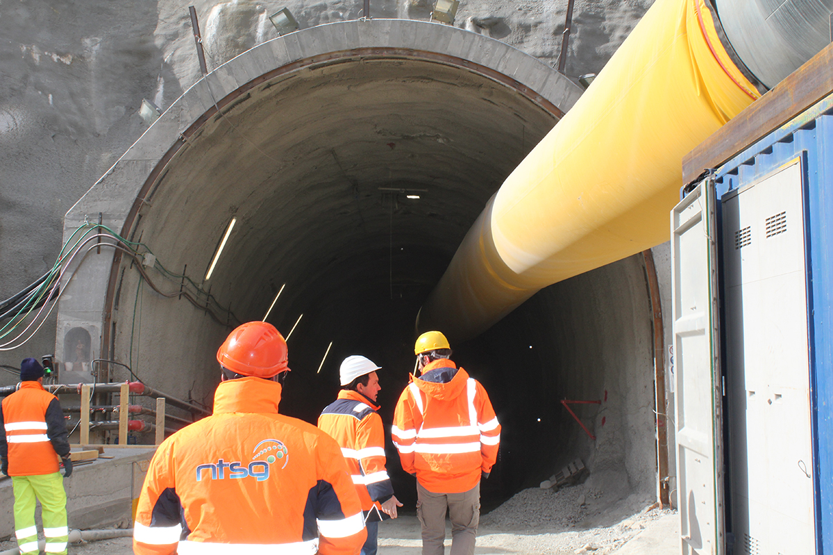
Location: Brennero Base Tunnel lot Isarco
Customer: BBT se
Project start date: 2016
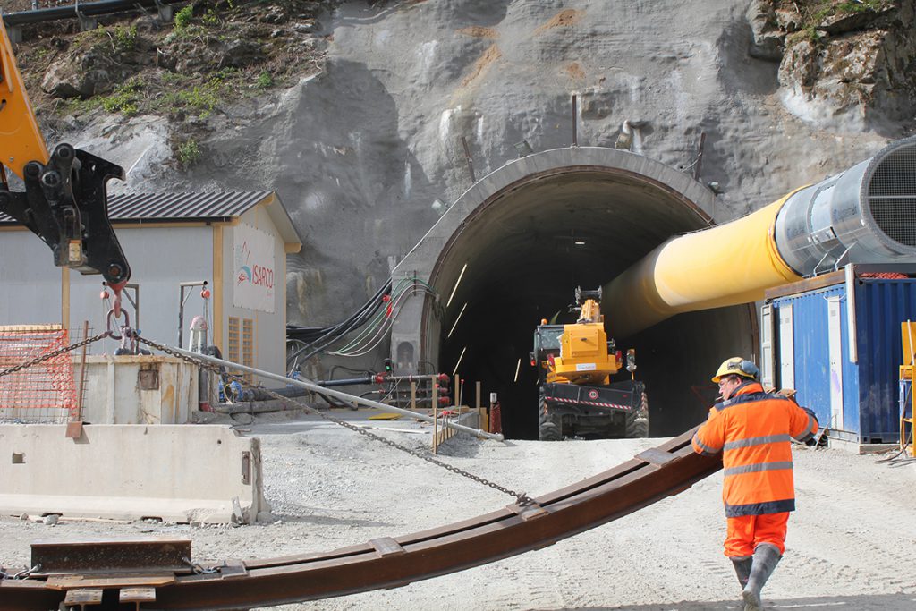
The required monitoring system involves the application of sensors capable of providing information such as: convergence measurements of the tunnel during the excavation phase, tensional state of the tunnel in the first phase and final, longitudinal deformations of the tunnel, pressures and loads of the first phase and definitive, contour deformations, excavation front deformations and final coating deformations. Outdoor measures of deformation and displacement of railway platforms, highways, state road, pylons, viaducts, decks, structures, subsoil. For the undercrossing section of the Isarco River, it is planned to install longitudinal Fiber Optic strain gauge chains at the height of the Plan of the Centers, so as to be able to detect any tensions and displacements of the tunnel caused by the dragging of the river subalveum
The Isarco tunnel project envisaged:
1. Monitoring for tunnel sections under the River Isarco
For the interconnections of the tunnel, passing under the river Isarco have been provided:
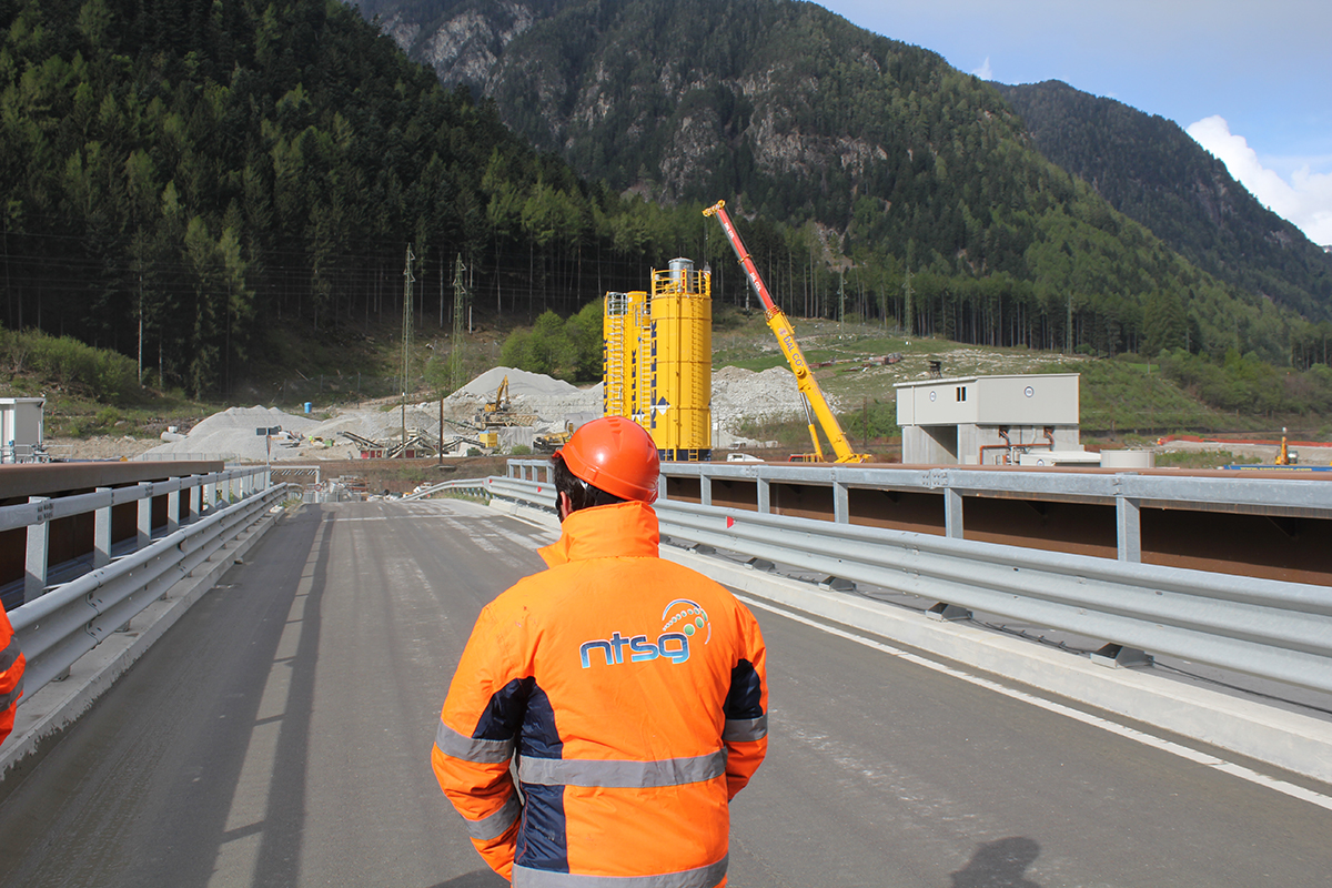
2. SURFACE MONITORING
Geotechnical monitoring on the surface has as its objective the following measures:
The infrastructures concerned are, above all, the 4 traffic infrastructures:
3. Monitoring of attack sections, escarpments, third-party works, infrastructures
The project includes the following measurements and measurement methods:
The monitoring subsystem of the area north of the River Isarco consists of:
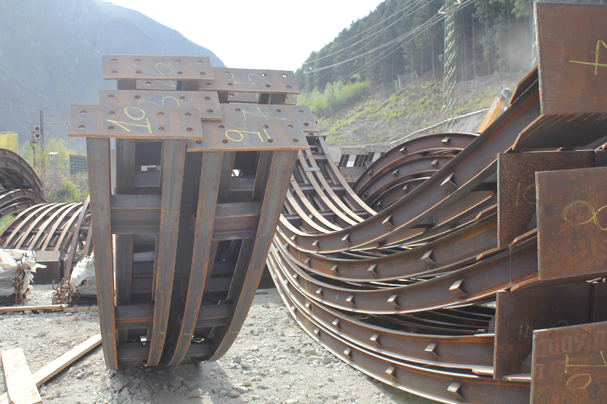
14 deep strain gauges equipped with 6 bases, of variable depth in correlation with the project, with the lower base placed at the height of the iron plane of the natural tunnel, and the subsequent 5 at step 1 meter towards the surface. Each workstation is implemented with a single Data Acquisition and Transmission Unit. The strain gauges will be aligned on n.03 cross-sections to the natural tunnels, and placed at a distance between 10 and 15 meters from the axis of the natural tunnels themselves.
The monitoring subsystem of the area south of the Eisack River consists of:
Each workstation is implemented with a single Data Acquisition and Transmission Unit. The strain gauges will be placed at a distance between 10 and 15 meters from the axis of the natural tunnels.
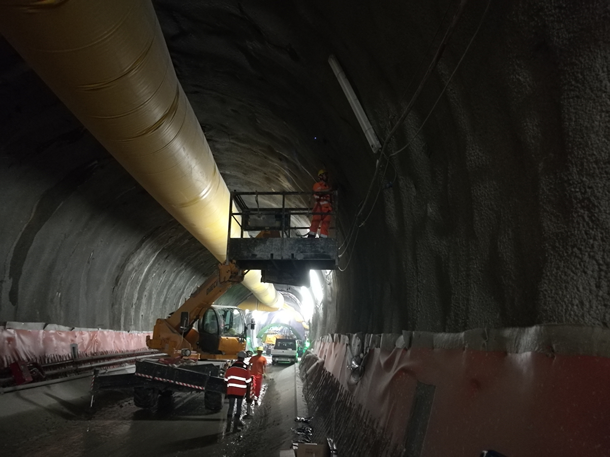
4. Monitoring of excavations of artificial tunnels
The following measurements and measurement methods are envisaged:
The monitoring subsystem consists of 11 instrumented sections, each consisting of:
5. Monitoring of well excavations
The following measurements have been carried out
The monitoring subsystem for the even Nord Binary Well consists of:
The monitoring subsystem for the even Sud Binary Well consists of
The monitoring subsystem for the Odd Track Well North consists of:
The monitoring subsystem for the South Odd Binary Well consists of:
The subsystems are complemented by: